
Capturing rotational and simulating data for high-speed rotating equipment such as engines, automated machines, and test rigs often plays a major role in industrial applications. Common applications include:
- Accurate speed measurement over a wide range of operations
- Detection of small speed variations
- Capturing phase or jitter
- Jitter simulation
- Angle-based data acquisition
This article presents practical approaches to accomplishing these tasks using ADwin data acquisition systems.
 Accurate Speed Measurement and Frequency Measurement over a Wide Range:
Speed signals are often measured from angular position signals generated by incremental encoders, which provide an output in the form of digital pulse sequences. These devices generate a fixed number of pulses per revolution, for example, 1024 pulses for each complete 360-degree rotation, so the number of pulses per unit of time is proportional to the rotational speed. In addition to this pulse train, most encoders will provide a separate reference pulse output that corresponds to 0.0 degrees to allow synchronization for absolute angular-based measurements.
At low rotational speeds, the measurement of the period between pulses requires a very precise reference time base. This can be provided by using a high-frequency reference clock signal (clock speed >20 MHz), which is used to calculate the time from rising to rising to the edge of the digital pulse output signal of the encoder, from which the period and speed can be calculated. As the rotational speed and the pulse frequency rise, this measurement becomes increasingly less accurate as the ratio of the measurement clock speed to the period of the speed-dependent encoder signal decreases.
To improve the accuracy at high rotational speeds, measuring the number of pulses over a fixed time interval will provide increased accuracy. Interestingly, in the mid-range, a combined frequency/period measurement is necessary to achieve acceptable accuracy. Here, the number of pulses N of the speed signal along with the N pulse period duration is recorded and then divided to get the period per individual pulse, resulting in a high-accuracy measurement in the intermediate range.
One difficulty remains, however, because one cannot assume that the incremental distance between the angle marks on the incremental encoder is the same. Linearity errors in incremental encoders are common, which challenges the engineer to make further considerations regarding speed detection. One possibility is as described above, where the speed is measured throughout N pulses, which results in an averaging over an angular range. The best results can be obtained by averaging over a full rotation, although even here the speed can be calculated several times during one revolution.
In the ADwin system, this is very simple: the reference output of the encoder is used to establish an angular reference point, and then for each pulse angle, the value of the period counter clock is stored in a table. On the following rotation, the difference between the new measured value of the clock and the value for the corresponding location recorded on the previous revolution is calculated to determine the speed. Then the new value of the period counter is stored in the table for measurement during the next revolution.
In the ADwin system, this is very simple: the reference output of the encoder is used to establish an angular reference point, and then for each pulse angle, the value of the period counter clock is stored in a table. On the following rotation, the difference between the new measured value of the clock and the value for the corresponding location recorded on the previous revolution is calculated to determine the speed. Then the new value of the period counter is stored in the table for measurement during the next revolution. A continuous recording of a speed variation is relatively easy to make by measuring the period for each complete revolution.
In the case where both the speed of revolution and the variation of speed over a longer period are of interest, the data can be directly evaluated online and analyzed by the processor of the ADwin system for statistical information such as minimum, maximum, and average values.
A Simulation of Angle-Dependent Quantities:
The key feature of an ADwin system is its local processor, which allows users to process each sampled measurement point to perform control even at high speeds. This capability is the basis for building a ‘jitter test.’ For example, an electric servo motor can be controlled via the ADwin’s outputs, using the rotation of the shaft to reproduce the behavior of the crankshaft of an internal combustion engine. This is used to test components such as camshafts, timing belts, fuel injectors, harmonic balancers, transmissions, etc. The electric motor simulates the rotation of an internal combustion engine with behavior that mimics the characteristics of real engine-based parameters such as the number of cylinders (2, 4, 6, 8, etc.), load and acceleration, or other rotational phenomena, which can be continuously adjusted via ADwin’s software.
In this application, the periodic rotational movement can be generated from an array where 360° of rotation is broken into 3600 individual nodes, allowing a resolution of 0.1 degrees. The calculation of the value output at each position is typically done in an initialization phase; for example, an array of values can be loaded into the ADwin system from a table previously defined on the PC, such as the output of a simulation tool. The table will contain the value for each 0.1-degree step, and the program is set to loop such that when the end of the table is reached, the program jumps back to the top of the table to read the next point until the number of tests cycles (revolutions) is reached. During the test, should a change in the amplitude, offset, or other characteristic be desired, it is not necessary to calculate a new table; rather, it’s enough to apply a calculation to the values in the table to determine a new output value for each output step.
This procedure applies to normal combustion engine operation. However, if users need to simulate additional non-recurring rotations, for example, when starting the engine, the table can be made correspondingly larger and may contain many more values. With more than 32MB of memory, the ADwin system can simulate the startup of an engine from a speed of 600 RPM generated by the starter motor to normal operation with an angular resolution of 0.1° and still allow a test sequence of more than 440 seconds. Both continuous and non-periodic modes can be combined to simulate a test in “blocks.” In this case, the sequence of tests is controlled based on a schedule switching between the various test segments, allowing the test duration to extend to hours, days, or weeks.
Angle-Based Control and Regulation:
An angle-based controller reads the current angle from one or more encoders at each sampling interval and computes the output from a table or formula to determine the corresponding digital or analog outputs. One simple application is using an ADwin as part of a vision system on a rotating part. The ADwin can continuously read the angular position of the part, even when it is spinning at high RPM. Then, it can trigger a camera or strobe light at a precise, repeatable angle so that the part appears “frozen” even though it is spinning. By continuously adjusting the angle, a 360-degree view of the part can be captured without stopping or slowing down the test. In essence, the part can appear in a video as if it is spinning at 3 RPM, even though it is spinning at 3000 RPM.
Other examples include a test stand for fuel injection pumps in internal combustion engines where the ADwin system controls the injector valves and a test bed for the new electronic valves in internal combustion engines, where (depending on the angle of the crankshaft) the valves are opened or closed under the control of the ADwin system. In many test benches or manufacturing machines, servo or stepper motors are used for position control. Here, the ADwin systems offer the possibility of providing simultaneous control across multiple axes. An interesting example comes from the manufacturing of pistons for internal combustion engines.
During the machining operation, the pistons are not made to be perfectly round but instead receive a slightly elliptical shape to compensate for unequal expansion, such that when they expand from the heat of normal operation, they assume an exact circular shape. During the machining, while the pistons are being rotated, the exact angle of rotation of the workpiece is measured, and then, from a table of reference angle vs. radius, an output value is determined for the controller, which adjusts the position of the tool used to shape the piston.
Intelligent Angle-Based Data Acquisition:
Angle-based measurements of analog and digital signals can easily be implemented when using ADwin systems, using an incremental encoder as the trigger source. Analog or digital signal inputs are sampled synchronously with the rising and/or falling edges of the encoder pulses. For this use, ADwin systems have analog inputs with parallel ADCs, which allow all analog inputs to be sampled simultaneously. With each pulse, all N analog inputs, digital inputs, or signals from the other ADwin input modules can be simultaneously recorded and stored.
The local intelligence of the ADwin system also allows data reduction. In this case, the measurements are restricted to a certain angular range, i.e., only valid measurement data within predefined areas is captured; outside these areas, the inputs are not measured or recorded. Another interesting possibility is the angle-dependent online analysis of measurement signals. Thus, for each angular step, parameters such as minimum, maximum, and average values are calculated from the analog inputs so that there are minimal, maximum, and mean curves from 0° to 360°. The capabilities of online evaluation are possible because of the freely programmable nature of ADwin systems, which provide virtually limitless possibilities.
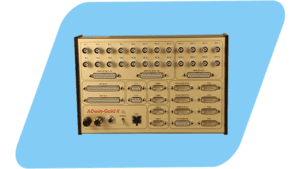
System Description:
ADwin system’s architecture combines analog and digital inputs and outputs, along with various other signal and communications interfaces with a high-speed local processor, local memory, and a highly optimized real-time operating system. The system is connected via Ethernet to a PC or Linux-based workstation. The application is partitioned into two parts: the time-critical part of the program runs on the local processor with the ADwin allowing microsecond-level deterministic operation while the less demanding part of the application such as the user interface visualization of data, and storage of measured results, runs on the workstation. Data can be seamlessly exchanged between these two environments via shared memory that is transparently managed by the ADwin driver software.
A Variety of Measurement & Control Capabilities:
Measuring and simulating data for high-speed rotating equipment such as engines, automated machines, and test rigs often plays a major role in industrial applications. Common applications include:
- Multiplexed and parallel (one per channel ADC) analog inputs
- Analog outputs
- Digital inputs and outputs,
- Counters, incremental encoders, and PWM interfaces
- RS-232/-485, Profibus, CAN-bus, and other Fieldbus interfaces
- Bootloader for stand-alone operation
ADwin’s real-time development environment enables the easy and fast creation of programs for time-critical systems. Drivers are available for a variety of PC applications on Windows or Linux. The included driver functions provide opportunities for exchanging data with ADwin systems, booting the system, downloading the program, and starting and stopping individual processes within the ADwin system.
One System, Many Applications
The ADwin system is a versatile and powerful tool for real-time data acquisition, control, and regulation. The examples described here for angle-based data acquisition, control, and regulation highlight just a few of the ADwin system’s possibilities. The system’s processor allows users to freely define the nature of their particular application, so complex applications have no set limits.
For further information on ADwin systems, or to find the ideal solution for your application-specific needs, contact a CAS Data Logger Application Specialist at (800) 956-4437 or request more information.