
Introduction
SDI-12 has become the environmental standard of choice for monitoring applications including environmental data collection, water and wastewater, industry regulatory compliance and many other fields. SDI-12 utilizes microprocessor-based ’smart’ sensors designed for environmental applications including flood warning, pollution monitoring, water temperature monitoring and more. The SDI-12 standard supports many intelligent capabilities such as automated data transfer–for example users can configure an SDI-12 data logger to automatically send their data to an office PC once a week so it’s ready every Monday morning. SDI-12 also enables automated alarms, control tasks such as activating a relay, capping a water sample, and many more time-saving tasks. At CAS DataLoggers we’ve put together this brief introduction to the SDI-12 standard highlighting the advantages your business or organization can realize from using SDI-12 data recorders and sensors.
What is SDI-12?
SDI-12 stands for Serial/Digital Interface at 1200 baud, being a serial-digital interface standard for microprocessor-based sensors. Since its release into the public domain in 1988, this standard offers users a low-power way to remotely send data, typically by using an SDI-12 sensor slaved to a master data recorder or data acquisition system.
SDI-12 is a communications protocol designed for environmental data collection, specifically as a way to interface battery-operated data acquisition devices with smart sensors utilizing microprocessors. The SDI-12 interface uses the SDI-12 bus (the cable connecting SDI-12 devices) to transmit serial data between one or more SDI-12 data recorders and sensors. Data can be collected, stored and transmitted in a variety of ways using this convenient standard.
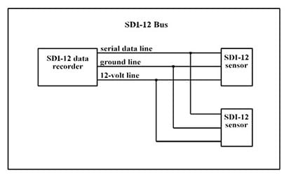
The SDI-12 standard’s bus is a cable with 3 conductors (3-wire):
- Serial Data Line
- Ground Line
- 12V Line– used to connect an SDI-12 data recorder with 1 to 10 SDI-12 sensors.
Figure 1 below is taken from version 1.3 of the SDI-12 standard and shows the SDI-12 bus (cabling) connecting one data recorder with two sensors. The SDI-12 bus is capable of having at least 10 sensors connected to it, each with 200 feet of cable. Using fewer sensors, users can run longer cable lengths.
General Benefits of Using SDI-12 Data Recorders & Sensors:
- Systems are low-cost and use just a single device to record data connected on one cable to one or more sensors;
- Power is supplied to sensors through the interface so SDI-12 recorders can operate unattended on battery power for extended periods;
- SDI-12 supports microprocessor-based sensors using EEPROMs (electrically erasable programmable read-only memory) which can apply complex calibration algorithms or internal computations.
How Does SDI-12 Handle Data Collection and Transmission?
All SDI-12 data recorder and sensor communications are transmitted on the data line in plain ASCII at 1200 baud with 7 data bits and an even parity bit. An SDI-12 intelligent (‘smart’) sensor is microprocessor-based, enabling it to take a recording (data sample), apply computations to that reading, and then use the SDI-12 standard to return the data scaled to engineering units. Some smart sensors can also self-calibrate if necessary.
SDI-12 communication occurs over one data line in a digital addressing system enabling a data recorder to communicate with ten or more sensors on the SDI-12 bus. An SDI-12 data recorder can also be interfaced with multi-parameter sensors to log two or more values such as temperature and humidity.
Specific SDI-12 Features Ideal for Environmental Monitoring:
- SDI-12 Data Recorders interface with many different sensor types, while SDI-12 sensors interface with many different data recorder models;
- Users can switch sensors without needing to recalibrate the data recorder;
- Compact design and easy installation lower time and cost of deployment;
- Smart sensors are frequently used as RTUs (remote telemetry units) to automatically send data to a desktop (at intervals such as once a week), further lowering service visit costs;
- Checksums have recently been added to the standard to detect errors in sensor data.
Example of SDI-12 Data Collection and Transmission:
- Communication begins when the SDI-12 data recorder (master) sends out a serial break signal to ‘wake up’ all connected sensors (slaves) from sleep mode and alert them to an incoming SDI-12 message. A break is a continuous spacing on the data line lasting at least 12 milliseconds.
- The data recorder sends an addressed sensor an SDI-12 command consisting of a string with two or more printable characters. For our purposes here the command tells the SDI-12 sensor to take a data measurement. Every command is for an individual sensor and is therefore disregarded by any other sensors located on the SDI-12 bus. The first character of an SDI-12 command is the sensor’s address which is a single character (usually 0 to 9) used to identify each sensor on the SDI-12 bus, and the last is an exclamation point (!)
Example of the Send Identification Command:
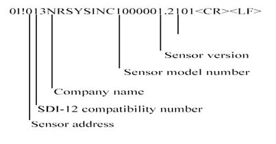
The SDI-12 standard also enables advanced commands to calibrate sensors, run diagnostic checks on sensors, and perform other sensor-specific tasks. These ‘smart’ features save users considerable time otherwise spent in configuration and setup.
- The addressed sensor immediately issues a service request to the data recorder telling it that the measurement is ready, or if not, the sensor will give the maximum time remaining until it is ready along with the number of data values it will give. The master should only receive a response from the slave whose address matches this message’s address.
- If the measurement is ready, the data recorder now commands the slaved sensor to transmit it. If the measurement is not ready, the data recorder must wait for the sensor to send a service request telling it that the measurement is ready as described above—when this happens the data recorder will then command the sensor to return the value. The sensor holds the most recent measurement in its ‘buffer’ memory where it’s stored until the sensor receives a new command.
- When its address is called, the matching preconfigured sensor will respond (here by transmitting its measurement) while any other sensors on the line remain in low-power standby mode (AKA ‘sleep mode’). An SDI-12 sensor’s response consists of a string with 3 or more characters which is returned to the data recorder. The first character of an SDI-12 response is the sensor’s address and the last two characters are a carriage return/line feed (). Other than the carriage return/line feed, all characters must be printable ASCII characters.
- (Optional): When the data recorder has finished collecting data from a given sensor, it is then free to communicate with another sensor, generally one at a time. The data recorder can also command the sensor to empty its buffer memory.
SDI-12 data recorders can also be used in Transparent mode to receive basic or extended commands from a modem or computer and then in turn transfer them to an SDI-12 sensor. One way users can utilize Transparent mode is by connecting a data logger’s serial port to a PC: after receiving a command input from the PC, the data logger transmits it to the sensor and sends its response back to the PC for display.
The SDI-12 Support Group distributes and upgrades the SDI-12 standard and is a good online source of information. The Group states that: “A serial-digital interface is a logical choice for interfacing microprocessor-based sensors with a data recorder…this has many advantages for sensors and data recorders.” The Group also cites that the U.S. Geological Survey uses over 4,000 SDI-12 sensors in its data collection networks.
Summary:
Today’s sensors are increasingly sophisticated, incorporating new monitoring and control capabilities. Owing to SDI-12’s convenient feature list and flexibility of application, the standard is likely to see continued years of use across several environmental and industrial applications. In particular the ability to automatically collect and transfer data will become even more commonly employed in a variety of regulatory and alarm projects.