
Processors with Sub-Microsecond Response Times Control a Variety of I/O
*Adapted from PID Control with ADwin, by Doug Rathburn, Keithley Instruments
By Terry Nagy, Computer Aided Solutions, LLC.
Introduction
One of the most common automatic control methods is the Proportional-plus-Integral-and-Derivative (PID) controller. Industrial controllers utilizing this technique are used for controlling processes like those found in chemical plants, those for temperature control, for certain automotive applications, etc. The purpose of a controller is to compensate for the effects of disturbances on process variables and to force a process variable to track a desired set point. While these controllers can be built using analog circuits, implementing them using a digital controller provides greater flexibility in adjusting the control algorithm and in fine-tuning the controller settings.
The PID controller measures the output of the process and calculates the difference (error) between what is measured and the set point. If an error exists, the controller adjusts its output to alter the process to bring it closer to the desired point, thus minimizing the error. Each time an error is calculated, the controller must decide how much to alter the process. If the controller is too aggressive (under-damped), it may cause the process to become unstable and oscillate. If control is not aggressive enough (over-damped), the system may require too much time to recover—or not recover at all.
The response characteristics of the controller are determined by the PID constants provided to the controller. The Proportional, Integral, and Derivative constants are used to calculate what the output should be relative to the measured error.
The Proportional constant represents the area in which the controller is actually controlling the process and determines the band of operation. It represents a constant that is multiplied by the error. While the proportion represents a constant multiplier of the error, as the error gets small, the effect of the proportion term also gets small. Simply increasing the magnitude of the proportion factor can lead to instability.
The Integral portion corrects for the offset between the set point and the process variable by automatically resetting or shifting the proportioning band. The integral accumulates the small constant error over time and forces the system towards the set point.
The Derivative constant determines the rate at which the controller reacts to large changes in the process variable.
Implementing a Digital PID Controller
 The architecture of the ADwin product family of data acquisition and control systems makes it well-suited for PID applications. In a Windows-based environment, response times can vary dramatically depending on what other applications are running on the PC. In fact it’s not uncommon to see up to 50 msec. response times which is often unacceptable for maintaining the level of control required in industrial or research process control. ADwin systems come with their own DSP processors with sub-microsecond response times that control a variety of I/O. The I/O includes ADCs (analog-to-digital converters), DACs (digital-to-analog converters), digital inputs, and digital outputs. Analog or digital inputs monitor the process, and the processor calculates the error between process output and the set point. A new output level for either analog or digital output is calculated to control the process.
ADCs for the ADwin products can be either 12- or 16-bit, while the digital inputs are either TTL, quadrature encoder, PWM, or up/down counters. The ADwin-PRO also has thermocouple and PTD input modules. For highly-optimized conditions, the ADwin hardware is capable of acquiring data at a rate of up to 1MHz, and input signals can be measured on both analog and digital inputs. The ADwin-GOLD has two ADCs for measuring two channels simultaneously and can be multiplexed across 16 inputs. The Pro-Ain-F family of analog input modules are well-suited for synchronized sampling. Each channel has a dedicated A/D to allow for parallel measurements, and the measurements can also be simultaneously triggered across multiple input modules.
Once the process is compiled onto the ADwin microprocessor and running, the process will run as long as it is connected to the power supply. The operating system on the host PC can ‘crash,’ but as long as the ADwin system is powered, the process will continue to execute. Therefore, the ADwin system’s processes run independently from the load of the PC processor. This continuous execution makes ADwin the ideal solution for fault-intolerant systems or where reliance on the host PC’s operating system is impossible. The ADwin-Gold and ADwin-Pro products also have boot loader options that allow them to be pre-programmed to run on power-up without the need of a PC.
Flow control is a very common use for PID controllers. This application involves controlling how much fluid or gas is flowing through a pipe with a valve. This volume is monitored and then controlled with the PID. The control steps are summarized here:
- Values for the desired flow and PID constants are passed to the ADwin processor.
- The flow sensor is measured using one ADwin analog input channel.
- The differential between what has been measured and the new set point is calculated.
- The error is added to all previous error terms that have been calculated.
- The sum of errors is compared to the limit of the valve. If the sum is too large or small, the sum is capped to correspond to a wide open or closed valve.
- The new position for the valve is calculated and then changed with one analog output channel on the ADwin.
- Return to Step 2 to continue the algorithm.
Available Input Types:
- Analog (12 & 16-bit)
- Digital
- Thermocouple
- RTD
- Counter/Encoder
- Quadrature
- PWM
Calculating the PID Constants
Calculating the constants that are used by the PID controller is the topic of much science and research. Likewise many books and methods exist for ‘tuning’ the controller to provide the desired response. Most methods provide values for each constant, but when the system is actually implemented, the system does not function properly. In fact, even the best methods typically only allow users to approach the correct constants, but for optimal operation for a specific controller and process variable, there is still an element of trial and error.
ADwin products easily allow for this trial and error. The programming language for the ADwin family is ADbasic. The hardware and ADbasic allow you to define integer and floating-point variables that are stored in registers that can be accessed while ADwin is running. The I/O registers can be easily accessed by most of today’s popular programming environments such as TestPoint™, LabVIEW™, Visual Basic, or C. The PID constants can then be passed to the appropriate register location and used by the ADwin processor during operation. Also, important process information can be read through one of the programs while ADwin is running.
PID Loop Timing and Multiple Controllers
The PID loop time is determined by how many times per second the output of the controller is updated. For a 1kHz loop, the inputs are measured and outputs changed for the controller 1000 times per second. A general rule of thumb states that the PID control loop should update twice as often as the physical parameter (e.g. temperature, lever position, valve, etc.) Therefore if the time constant of this physical parameter is one second, then the control loop should be updated every 0.5 seconds. Typical industrial PID controllers update at 1kHz, while other real-time controllers are generally capable of only about 5kHz.
ADbasic enables quick and simple development of different control structures in addition to the PID, but it is possible to construct a PID loop for ADwin at 500kHz (100% CPU load). As the control loop speed is decreased, the load on the CPU is also reduced. Therefore, a PID control loop running at 50kHz could require only about 10% of the ADwin CPU, and a 20kHz loop uses approximately 4%.
For control loops running at less than 500kHz, excess processor bandwidth is available to run multiple controllers on the same ADwin hardware. These multiple controllers could be either cascaded or independent. The controllers can also run at different frequencies or cycle times.
Equipment List:
- PC running Windows (95/98/ME/NT/2000/XP/Windows 7)
- ADwin real-time control hardware
- ADbasic real-time development environment
- Custom wiring harness for connecting to test setup
Alternative Solutions
The ADwin product family offers many different form factors, processors, and I/O in which to create the PID controller. The ADwin family includes:
ADwin-Light-16 Plug-in boards and external systems
- Analog inputs and outputs (one 12-bit A/D)—expandable
- Digital I/O
- Optional counters
- PCI, USB or Ethernet communication with the PC
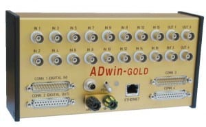
ADwin-GOLD Stand-alone, external system
- 16 analog inputs (16-bit @ 10ms & 12-bit @ 0.8ms)—BNC connections
- 2 analog outputs (16-bit)—expandable
- 32 digital I/Os, in block of 8 as input or output
- Optional counter (event counter, encoder interface, period cycle, PWM)
- Integrated USB or Ethernet communication with the PC
ADwin-PRO Industrial, modular 19-inch system
- Up to 4 CPUs per system
- Modular and expandable:
- 480 analog inputs (multiplexed or parallel)
- 120 analog outputs
- 480 digital I/Os
- Thermocouples, RTD, counter, filters, isolation, etc.
- CAN-bus, Profibus, RS-232, RS-485, RS-422
- USB or Ethernet for communication with the PC
In addition, the ADwin-Gold and ADwin-Pro can support up to 32Mbytes of RAM per processor and optional bootloader. The bootloader stores an ADbasic process(es) and begins running the process upon power-up. Therefore, once the ADwin hardware is programmed, it can be used as a stand-alone solution without a PC.