
Wheatstone bridge circuits are commonly used to measure small changes in resistance, such as the output of strain gauges and other sensors. They offer high measurement sensitivity and temperature compensation. dataTaker data loggers fully support the measurement of Wheatstone bridge circuits in full, half, and quarter bridge configurations. For a quick overview of the dataTaker Geotechnical loggers, view the product video.
The dataTaker supports two methods of Wheatstone bridge measurement:
- excitation of sensors using a constant current source
- excitation of sensors using a voltage source
Both of these methods of bridge support can have a number of options, depending on the number of active arms in the bridge and the number of wires used to connect bridges to the dataTaker data logger.
Constant Current Excitation of Bridges
The constant current excitation method of bridge measurement utilizes a current of 2.500 mA or 200.0 μA for excitation. The advantage of using this method is that the bridge sensitivity and zero offset is independent of the length of leads used to connect the bridge to the dataTaker, so this method is particularly useful if long lead wires (25 feet or greater) are used to connect the logger to the sensor. In some cases, the bridge output can have greater linearity and reduced temperature sensitivity for constant current excitation than for voltage excitation.
The bridge excitation current is supplied between the Excite (*) terminal and the Return (#) terminal of the analog input channel during measurement. Note that the current is only applied for approximately 50 milliseconds so it will be difficult to measure using a standard meter. The current is applied for approximately 10 milliseconds before the bridge voltage measurement is initiated. In the case of long cables which might have significant capacitance, this delay can be increased using the MDn channel option where n is the delay time in milliseconds. By default, the bridge excitation current is 2.500 mA but may be set to 200.0 μA if required. The 2.500 mA current provides the best resolution for typical 350-ohm strain gauges, but the smaller current can be used if the strain gauge resistance is greater than 700 ohms or if the self-heating of the bridge sensor is a concern. If the 200.0 μA excitation current is required, then this is specified as a channel option in the channel specification using the I channel option.
The Arm Resistance
The data that is returned by the data logger from bridge circuits excited with a constant current is the ratio of the change in arm resistance to the nominal arm resistance. The data is returned in units of ppm (see below). The arm resistance for the bridge being measured must be known by the dataTaker and is specified as a channel option in the channel specification. The default arm resistance is 350 Ohm, which is typical for many types of strain gauges. For higher accuracy, if the actual arm resistance is available from the data sheet or if the bridge resistance is not 350 ohms, the arm resistance can be specified as a channel option Ohms.
Full Bridge with Constant Current Excitation
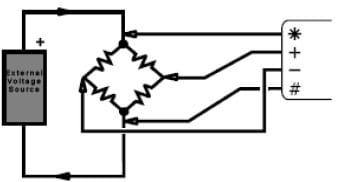
The dataTaker can provide excitation and measure the output from a full bridge of devices such as strain gauges, pressure cells, load cells, etc. This configuration is a 4-wire input and supports 1, 2, or 4 active arms. Any of the bridge arms can be active arms. The configuration also provides compensation for cable wire resistance, allowing long cable wires to be used. Bridge arms that are not active must have bridge completion resistances. These can be inactive devices of the same type as the devices on the active arms, or these can be a resistor with the same resistance value as the active devices at rest, and ideally have a temperature coefficient that is similar to that of the active devices. The entire bridge circuit is external to the dataTaker – the logger does not provide any bridge completion for partial bridges. The full bridge configuration with constant current excitation is connected to the dataTaker as a 4-wire input:
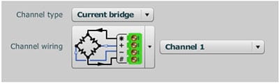
where the Excite terminal provides current excitation of 200.0 μA or 2.500 mA, which returns via the Analog Return (#) terminal. The bridge output is read between the + and – terminals.
Interpreting the Data from a Full Bridge with Current Excitation
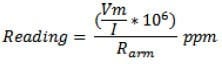
The data returned from full bridges is the ratio of change in measured resistance to the arm resistance, expressed in parts per million as follows:
Where:
- Vm is the measured voltage
- I is the excitation current
- Rarm is the nominal arm resistance
Calculating Microstrain for Full Strain Gauge Bridges
When using stain gauges in full bridges, it may be desirable to convert the returned data from units of ppm to units of Microstrain. This can be done by the following formula:
![]()
Half Bridge with Constant Current Excitation
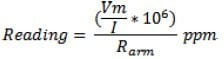
The dataTaker can also provide excitation and measure the output from a half-bridge configuration of strain gauges, pressure cells, etc. This configuration is a 3-wire input that supports 2 active arms. This configuration compensates for cable wire resistance and temperature difference. The half-bridge configuration with constant current excitation is connected to the dataTaker as a 3-wire input.
In this case, Ra and Rc are the 2 active arms of the half-bridge. Note that a jumper is required between * and + terminals. As before, the result of the measurement is returned in ppm which is the effective change in resistance of the bridge multiplied by 106. When using stain gauges in half bridges and current, it may be desirable to convert the returned data from units of ppm to units of Microstrain. This can be done by the following formula:
![]()
or
![]()
This half-bridge method of strain gauge measurement has a measurement resolution of approximately 0.2 Microstrain.
Quarter Bridge with Constant Current Excitation
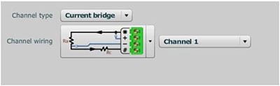
The quarter bridge configuration for measuring bridges is a variation of the half-bridge configuration, where there is one active device (such as a strain gauge) and a bridge completion resistance to balance the bridge. The bridge completion resistance can be an inactive device of the same type as the active device or can be a resistor with the same resistance value as the active device, and ideally has a temperature coefficient similar to that of the active device. The entire bridge circuit is external to the dataTaker – the logger does not provide any bridge completion for partial bridges. Quarter bridges with constant current excitation are connected to the dataTaker as follows:
In this case, Ra is the active arm of the quarter bridge and Rc is an external bridge completion resistor. Note that a jumper is required between * and + terminals. As before, the returned value is:
In this case, for accurate results, it is important that the bridge completion resistor Rc have a resistance that is equal to the active arm of the bridge at rest to properly balance the bridge (measured voltage =
0.0 with no load applied). To convert data from units of ppm to units of Microstrain, the standard formula becomes:
![]()
Voltage Excitation of Bridges
The alternative method for measuring bridge circuits with the dataTaker is voltage excitation with ratiometric measurement. The principle of the method is that the bridge is excited by a constant voltage source and the bridge output voltage is measured as a ratio of the measured voltage to the excitation voltage. In practice, the resistance of the cable wires connecting the bridge to the logger reduces the excitation voltage that is actually applied to the bridge, which in turn results in a proportionate loss of output signal voltage from the bridge. To correct this error, the actual voltage applied across the bridge is measured using a second channel.
The Bridge Excitation Voltage Source
The bridge excitation voltage, also often referred to as the bridge power supply, can be supplied from a number of sources:
- the internal voltage excitation source of the dataTaker via the Excite (*) terminal of the analog channel, which can output a nominal 5 Volts (actually nearer 4.5 Volts);
- the switched 12 Volt sensor power supply terminal of the dataTaker, which is limited to 100 mA total current draw;
- the switched 5 Volt sensor power supply terminal of the dataTaker (Series 3 only) which is limited to 25 mA total current draw;
- or an external voltage source either directly connected to the bridge or switched through the EXT */# terminals.
The bridge excitation voltage must be switched on during the period of measurement. If the internal voltage excitation source is used, it will be automatically switched on by the logger at appropriate times. If an external voltage source is used for excitation, the bridges can be either permanently powered or can be powered only during measurement by using the external excitation terminals of the data logger. The default for the internal voltage source for bridge excitation is the unregulated 5-volt supply from the Excite terminal and is automatically selected when bridge inputs with voltage excitation are specified. However, if the bridges are powered from external sources connected directly to the bridge, then the Excite terminal voltage should be disabled using the N channel option. If the bridge is to be powered from external sources connected through the external excitation terminals, EXT */#, then the external excitation option should be enabled using the E-channel option.
Measuring the Bridge Excitation Voltage
In practice, the resistance of the cable wires connecting bridges to the dataTaker reduces the excitation voltage that is actually applied to the bridge. This results in a proportionate loss of output signal from the bridge. To correct this error, the actual excitation voltage across the bridges is also measured. The bridge excitation voltage is connected as a differential or single-ended voltage input to any analog input channel and must be measured immediately before the output of any bridge is measured. This measurement is referred to as the ‘bridge reference voltage’, and is measured on the bridge reference channel that is identified to the dataTaker by the BR channel option for the particular channel. This can be on the same channel as that being used for the actual bridge signal voltage or on a different channel.
Note that if the excitation voltage is greater than 3.0 volts, it might seem possible to use the HV channel type to measure the bridge excitation voltage, but this is not recommended since the measurement accuracy when using this channel type is normally not sufficient for bridge applications. In this case, it is better to use the bridge itself to attenuate the voltage being sourced and then use a scale factor to allow the data logger to calculate the actual excitation voltage.
To measure the excitation voltage in dEX, use the appropriate channel in the channel wiring screen or use Manual Channel Type with the following commands:
| bridge output | reference excitation measurement |
| 3V supply | 1*V(BR,W) |
| 6V supply | 1+V(2,BR,W) |
| 5.00V supply | Not Required |
Notes:
1. The bridge reference channel must precede the bridge measurement channel(s) in the dataTaker program because the bridge reference voltage is used to calculate the bridge data for the subsequent bridge measurement channels.
2. If bridge measurements are included in more than one Schedule, then the bridge reference channel(s) must be declared in each Schedule.
3. If a bridge reference channel is not declared, then the bridge reference voltage defaults to 5 Volts.
Full Bridge with Voltage Excitation
The full bridge with voltage excitation configuration is the more traditional method for the measurement of bridge outputs. However, fully implementing this requires more resources than any of the constant current methods, requiring two channels for each bridge if each bridge has a separate bridge excitation. If a shared excitation source is used, two channels are required for the first bridge, with one channel for each additional bridge that is excited by the same power supply. This configuration is only appropriate if all cable wires are the same length, such that all bridges receive the same voltage excitation as measured for the first bridge. This configuration supports 1, 2, or 4 active arms. Any of the bridge arms can be active arms. Bridge arms that do not have active devices must have bridge completion resistances to balance the bridge. These can be inactive devices of the same type as the active devices or can be a resistor with the same resistance value as the active devices at rest, and ideally have a temperature coefficient that is similar to that of the active devices. Also, the entire bridge circuit is external to the dataTaker – the logger does not provide any bridge completion for partial bridges.
Interpreting the Data from a Full Bridge with Voltage Excitation
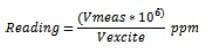
Data returned from full bridges with voltage excitation is calculated as the ratio of the change in bridge output voltage to bridge excitation voltage, expressed in parts per million as follows:
![]()
Calculating Microstrain for Full Strain Gauge Bridges
When using stain gauges in full bridges, it may be desirable to convert the returned data from units of ppm to units of Microstrain. This can be done using the following formula:
![]()
This full bridge method of strain gauge measurement has a resolution of approximately 0.2 Microstrain.
Half Bridge with Voltage Excitation
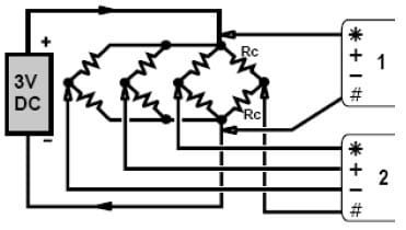
Half bridges with two active arms and voltage excitation are commonly used when a large number of bridges need to be located in close proximity. The dataTaker supports this configuration by using single-ended inputs. Half bridges with two active arms require two bridge completion resistances to balance the bridge. The two bridge completion resistances can be either inactive devices of the same type as the active device or can be a resistor with the same resistance value as the active devices, and ideally have a temperature coefficient similar to that of the active devices. This half-bridge configuration with voltage excitation can be used to measure a single half-bridge or to measure a number of half-bridges that share the same bridge excitation voltage supply, and share the same set of bridge completion resistors. Multiple half-bridges that are excited from a single excitation voltage source and that share bridge completion resistors are illustrated below.
Interpreting the Data from a Half Bridge with Voltage Excitation
Data returned from half bridges with voltage excitation is calculated as the ratio of the change in bridge output voltage to bridge excitation voltage, expressed in parts per million as follows:
Calculating Microstrain for Half-Strain Gauge Bridges
When using stain gauges in half bridges, it may be desirable to convert the data from units of ppm to units of Microstrain. This can be done via the standard formula:
![]()
Converting Bridge Outputs to Engineering Units
So far, methods have been provided to convert measured bridge output in ppm to units of Microstrain for the various bridge configurations. However, units of Microstrain apply to strain gauge bridges which
are measuring deformation. Many sensors available today employ a bridge circuit to sense the parameter they are designed to measure. For example, some pressure cells, load cells, micro-displacement transducers, etc. in fact contain a diaphragm or similar structure which has a full strain gauge bridge bonded to one surface. The diaphragm is mechanically distorted by the pressure or load, which is measured by the strain gauge bridge. This distortion is calibrated to units of pressure, load, etc. by the manufacturer. Supporting these types of sensors with the dataTaker is quite simple, as shown by the following examples.
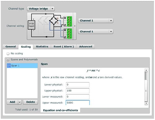
Pressure Transducer
A pressure transducer that is constructed as a full bridge device with a 4-wire connection, is connected to the dataTaker as a full bridge with constant current excitation (type BGI). The transducer has an output of 0.05 V full scale at 10 VDC excitation for a full-scale pressure of 100 PSI. The dataTaker will measure:
At minimum bridge output (0.0 psi) = 0.0 ppm
At full-scale output = 5000 ppm at 100 PSI
Therefore 1ppm = 100 PSI/5000 ppm = 0.02 PSI. This transducer calibration can be used in a dataTaker program to return the data in units of PSI so that it is a simple matter of constructing a scaling conversion to convert ppm to PSI.
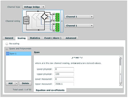
Load Cell
A load cell that is constructed as a full bridge device with a 4-wire connection is connected to the dataTaker as a full bridge with constant current excitation (type BGI). The load cell measures a load of 100 lbs full scale and has an output of 2.0006 mv/V at full scale. The dataTaker will measure:
At minimum bridge output (0.0-pound load) = 0.0 ppm
At full-scale output = 2000.6 ppm at 100-pound load
Therefore 1 ppm = 100 lbs / 2000.6 ppm = 0.049985 lbs. This transducer calibration can be used in a dataTaker program to return the data in units of lbs.
Measurement Ranges and Accuracy
The dataTaker measures all bridge inputs as a low-level voltage, with a resolution of 0.25 μV, and a nominal accuracy of 0.1%. The accuracy for particular applications can be calculated from this information and the excitation current or voltage used.
Error Messages
There are no specific error messages for bridge inputs. However, input voltage signals which fall outside the voltage range of the dataTaker will produce an over-range reading of –99999.9 ppm or +99999.9 ppm. The dataTaker also reports the error condition with the error message ‘E11–input(s) out of range’ if the Messages Switch /M is enabled.