Description
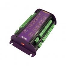
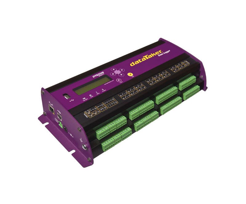
DT85GM Geotechnical Data Logger
The new DT85GM Geotechnical Data Logger Series 4 version has increased sampling speed, measurement range, and programmable analog output.
Advanced design and technology plus 25 years of geotechnical expertise have produced the dataTaker DT85GM GeoLogger – A versatile, powerful – yet low-power & cost-effective data logger.
It supports vibrating wire and other geotechnical sensors such as Slope Indicator, RST Instruments, Geokon, Soil Instruments, Roctest, AGI – Applied Geomechanics Inc. DT85GM is also capable of testing sensor integrity through audible frequency
With temperature compensation (thermistor), 16 analog channels are capable of reading up to 16 vibrating wire sensors. If temperature compensation is not required this logger can read up to 48 vibrating wire sensors.
Further expansion up to 320 sensors (with temperature compensation) or 960 sensors (without temperature compensation) is possible.
Designed For Remote Applications
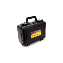
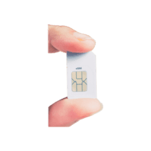
The dataTaker DT85GM intelligent data logger is a fully featured low-powered logging platform with an integrated cellular modem, making it perfect for remote applications. The rugged design and wide operating temperature range of the DT85GM provide reliable operation in virtually any environment.
The DT85GM’s perfect balance of performance with low power also allows you to use a smaller solar panel without compromising on functionality.
Automatic Data Delivery
Forget traveling long distances to get your data. Utilize the DT85GM’s automatic data delivery features to schedule your data to be automatically emailed to your inbox every day, week, month or other time intervals.
More sophisticated systems can make use of the automatic data delivery features to send logged data to an FTP server. Alarm conditions can also trigger data delivery in addition to sending alarm messages to multiple email addresses or mobile phones.