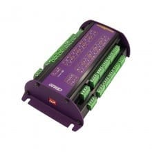
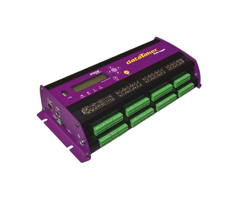
DT85M Intelligent Universal Input Data Logger
Datataker DT85M Data Logger with built in cellular modem
|
Product Overview
Useful Links
|
Designed For Remote Applications
The dataTaker DT85M intelligent data logger is a fully featured low-powered logging platform with an integrated cellular modem, making it perfect for remote applications. The rugged design and wide operating temperature range of the DT85M provides reliable operation in virtually any environment.The DT85M’s perfect balance of performance with low-power also allows you to use a smaller solar panel without compromising on functionality.
Automatic Data Delivery
Forget travelling long distances to get your data. Utilise the DT85M’s automatic data delivery features to schedule your data to be automatically emailed to your inbox every day, week, month or other time interval. More sophisticated systems can make use of the automatic data delivery features to send logged data to an FTP server. Alarm conditions can also trigger data delivery in addition to sending alarm messages to multiple email addresses or mobile phones.
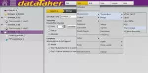
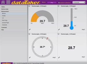
Easy To Configure
The DT85M is configured directly in your web browser using dataTaker’s dEX graphical interface. dEX takes you through the configuration of your logger, showing you wiring diagrams and allowing you to decide – in as much or as little detail – how you want to the system to work, suiting both novice or advanced users. Using the internal modem you can even re-configure your system remotely over the internet if required.
| Inbuilt Modem | |
|---|---|
| Features |
Alarms: Send email or SMS messages Data: Send data to an email address or FTP server Remote access: Connect to dEX or Command interface SIM interface: SIM Socket (1.8V/3V) |
| Networks Interfaces |
USA Only: EDGE, GPRS, GSM, CSD All Other places: EDGE, GPRS, GSM, WCDMA, HSUPA, HSDPA |
| Frequencies |
EDGE/GPRS/GSM: 850/900/1800/1900 MHz WCDMA/HSUPA/HSDPA: 850/1900/2100 MHz |
| Analog Channels | |
| Analog Channels |
2 Wire w/ Com. Ref. Terminal: 48 Channels (expandable to 960*) 2 Wire Isolated: 32 Channels (expandable to 640*) 3 or 4 Wire Isolated: 16 Channels (expandable to 320*) * - Expansion requires optional CEM20 |
| Analog Inputs |
Inter-Channel Isolation: 100 Volts (Relay Switching) Analog Section Isolation: 100 Volts (Opto-Isolated) Input Impedance: 100 KO, >100MO Common Mode Range: ±3.5V or ±35V on 30 Volts Range |
| Analog Measurement Ranges |
Voltage: ±30 mVdc; ±300 mVdc; ±3 Vdc; ±30 Vdc Current: ±0.3 mA; ±3 mA; ±30 mA Resistance: 100O; 1,000O; 10,000O Frequency: 100Hz; 10 kHz |
| Analog Measurement Resolution |
Voltage: 0.25µV; 2.5µV; 0.25µV; 250µV Current: 2.5nA; 25 nA ; 250 nA Resistance: 1.5 mO; 15 mO; 150 mO Frequency: 0.0002%; 0.0002% |
| Accuracy |
DC Voltage: 0.1% (5°C to 40°C); 0.35% (-45°C to 70°C) DC Current: 0.15% (5°C to 40°C); 0.45% (-45°C to 70°C) DC Resistance: 0.1% (5°C to 40°C); 0.35% (-45°C to 70°C) Frequency: 0.1% (5°C to 40°C); 0.25% (-45°C to 70°C) |
| Sampling |
Integrates over 50/60 Hz Line Period for Accuracy and Noise Rejection Maximum Sample Speed: 25 Hz Effective Resolution: 18 Bits Linearity: 0.01% Common Mode Rejection: >90dB Line Series Mode Rejection: > 35dB |
| Sensor Excitation (Supply) |
Analog Channles: Selectable 250µA or 2.5mA Precision Current Source, 4.5V Voltage Source, or Switched External Supply General Purpose: Switchable 12V Regulated Supply for Powering Sensors & Accessories (Max. 150mA) |
| Analog Sensors | |
|---|---|
| Thermocouples |
Type: B, C, D, E, G, J, K, N, R S, T Calibration Standard: ITS-90 |
| RTDs |
Materials Supported: Pt, Ni, Cu Resistance Range: 10O to 10KO |
| Thermistors |
Type: YSI 400xx Series, other Types* Resistance Range: <10kO** * Other Thermistor Types are Supported by Thermistor Scaling and Calculated Channels ** Resistance Range Can Be Increased with the Use of a Parallel Resistor. |
| Monolithic Temperature Sensors | Type: LM34 - 60, AD590, AD592, TMPxx, LM135, LM235, LM335 |
| Strain Gauge and Bridge Sensors |
Configurations: 1/4, 1/2 & Full Bridge Excitation: Voltage or Current |
| 4-20mA Current Loop | Internal 100R Shunt or External Shunt Resistor |
| Digital Channels | |
|---|---|
| Digital Input/Outputs |
8 Bi-Directional Channels Digital Input Type: 8 Logic Level (Max. 20/30 Volts) Digital Output Type: 4 With Open Drain FET (Max. 30V, 100mA), 4 with Logic Output |
| Relay Output | 1 Latching Relay, contacts (Max: 30Vdc, 1A) |
| Counter Channels | |
|---|---|
| Low Speed Counters |
-- 8 Counters Shared with Digital Inputs -- 32 Bit Size -- 10 Hz Max Count Rate -- Low Speed Counters do not Function in Sleep Mode |
| Dedicated Counter Channels |
-- 4 High Speed Inputs or 2 phase encoder (quadrature inputs) -- 32 Bit Size -- 100kHz Max Count Rate -- 2 Logic Level Inputs (Max ±30V) -- 2 Sensitive Inputs (10mV) for Magnetic Pick Ups (Max. ±10V) |
| Serial Channels | |
|---|---|
| SDI-12 |
-- 4 SDI-12 Inputs, Shared with Digital Channels -- Each input can support multiple SDI-12 Sensors |
| Calculated Channels | |
|---|---|
| General | Combine values from analog, digital and serial sensors using expressions involving variables and functions. |
| Functions | Arithmetic, Trigonometric, Relational, Logical and Statistical |
| Alarms | |
|---|---|
| Condition | High, Low or Within Range and Outside Range |
| Delay | Optional Time Period for Alarm Response |
| Actions | Set Digital Outputs, Transmit Message, Execute any DataTaker Command |
| Scheduling of Data Acquisition | |
|---|---|
| Condition | High, Low or Within Range and Outside Range |
| Number of schedules | 11 |
| Schedule rates | 10ms to days |
| Internal Data Storage | Capacity: 128mb = approx 10,000,000 data points |
| Removable USB storage device |
Type:compatible with USb 1.1 or USB 2.0 drivers, e.g. Flash drive Capacity: approx 90,000 data points per megabyte |
| Communication Interfaces | |
|---|---|
| Ethernet Port |
Interface: 10BasteT (10Mbps) Protocol: TCP/IP |
| USB Port |
Interface: USB 1.1 (virtual COM port) Protocol: ASCII command |
| Host RS232 Port |
Speed: 300 to 115,200 Baud (57,600 Default) Flow Control: Hardware (RTS/CTS), Software (XON/XOFF), None Handshake Lines: DCD, DSR, DTR, RTS, CTS Modem Support: Auto-Answer and Dial Out Protocols: ASCII Command, TCP/IP (PPP), Serial Sensor, Modbus |
| Serial Sensor Port |
Interface: RS232, RS422m, RS485 Speed: 300 to 57,600 baud Flow Control: Hardware (RTS/CTS) Software: (XON/XOFF), None Protocols: Modbus (master & slave), Serial Sensor |
| Network TCP/IP Services | |
|---|---|
| Network | Ethernet and/or Host RS232 (PPP) Communication Ports |
| Command Interface | Access the ASCII command interface via TCP/IP |
| Web Server |
-- Access Current Data and Status from any Web Browser -- Download Data in CSV Format -- Command Interface Window -- Define Mimic Displays |
| Modbus Server(slave) | Access current data and status from any Modbus client |
| Modbus Client(master) | Read/Write data from Modbus sensors and devices including PLC's dataTaker loggers, modbus displays, etc. |
| Email Client | Email data or alarms directly from the logger |
| DDNS Client | Brwose to the logger over the Internet using Dynamic DNS |
| FTP Server | Access logged data from any FTP client or web browser |
| FTP Client | Automatically upload logged data direct to an FTP server. |
| System | |
|---|---|
| Display and Keypad |
Type: LCD, 2 Line by 16 Characters, Backlight Functions: Channel Data, Alarms, System Status Keypad: 6 Keys for Scrolling and Function Execution Status LEDs: 4 (Sample, Disk, Attention, Power) |
| Firmware Upgrade | Via: RS232, Ethernet, USB disk. |
| Real Time Clock |
Normal resolution: 200µs Accuracy: ±1 min/year (0°C to 40°C), ±4 min/year (-40°C to 70°C) |
| Power Supply |
External Voltage Range: 10 to 30 Volts DC Peak Power: 12W |
| Average power Consumption (typtical) |
1 Sec Sampling: 560 mW (1 Sample); 926 mW (6 Samples) 5 Sec Sampling: 250 mW (1 Sample); 337 mW (6 Samples) 30 Sec Sampling: 50 mW (1 Sample); 65 mW (6 Samples) 1 Min Sampling: 30 mW (1 Sample); 38 mW (6 Samples) 5 Min Sampling: 14 mW (1 Sample); 16 mW (6 Samples) 30 Min Sampling: 11 mW (1 Sample); 11 mW (6 Samples) 1 Hr Sampling: 11 mW (1 Sample); 11 mW (6 Samples) |
| Physical Environment | |
|---|---|
| Construction | Powder Coated Steel & Anodized Aluminum |
| Dimensions | 300 x 137 x 65mm |
| Weight | 2.5kg (5kg shipping) |
| Operating Range |
Temperature: -45°C to 70°C (Reduced LCD Operation Outside Range: -15°C to 50°C) Humidity: 85% RH, Non-condensing |
dEX Software
dEX is an intuitive graphical interface that allows you to configure your data logger, view real-time data in mimics, trend charts or tables and retrieve your historical data for analysis.
dEX runs directly from your web browser and can be accessed either locally or remotely, anywhere that a TCP/IP connection is available including worldwide over the Internet. You can use any of the logger’s built-in communications ports to view dEX including Ethernet, USB and RS-232.
- Built-in software - no application to install
- Runs directly from your web browser
- Accessible by Ethernet or USB connection
- Intuitive graphical interface
- Easy-to-use configuration editor
- Access live and historical data
- View data charts, mimics and tables
Real Time Trending
Real-time trending for sensors, calculations or other data. Supports up-to 5 traces per chart and up-to 2 Y-axes. Backfills with historical data stored in logger.
Real Time Displays
dEX displays real-time sensor measurements, calculations and diagnostic information, including mimics, tables and trend charts
Configuration Made Easy
The configuration editor allows you to view, edit and save logger configurations in an easy-to-use Windows Explorer style user interface. Tree view of configuration allows definition of measurement schedules and measurements.
Wiring diagrams show possible wiring configuration for selected sensor type. Configuration can be stored and retrieved on either the logger or a local computer

|
|
20 Channel Expansion Module CEM20A dataTaker CEM20 connects to one analogue channel of the dataTaker data logger. Each CEM20 connects 20 universal data logging channels.
|
|
|
CANgate CANbus to Serial ConverterThe dataTaker CANgate CAN to ASCII gateway filters and converts CAN (Controller Area Network) and GPS (Global Positioning System) data to serial ASCII data.
|
|
|
Portable Enclosure
|
|
|
Industrial Enclosure
|
Request Pricing & Information
If you need information right away or prefer to speak with a person, call us and one of our Experienced Applications Engineers will be happy to talk with you. You can reach us at 1-800-956-4437 during our normal business hours Monday - Friday from 8am to 6pm (EDT).
After filling out the form below, an applications engineer will contact you within at least one business day.
* Indicates a required field.
Fields that are not required are recommended to be filled out so that we can better assist you.


