dataTaker DT80

5 Channel Universal Input Data Logger

  • Up to 15 Analog (± 50V) sensor inputs
  • Expandable to 300 analog inputs
  • 12 flexible digital terminals
  • 2 Serial ‘Smart Sensor’ ports
  • SDI-12 (multiple networks)
  • Programmable Analog Output
  • Modbus for SCADA connection
  • Web & FTP client / server
  • USB memory for easy data and program transfers

$2,870.00

Normal delivery 1-2 weeks

Description

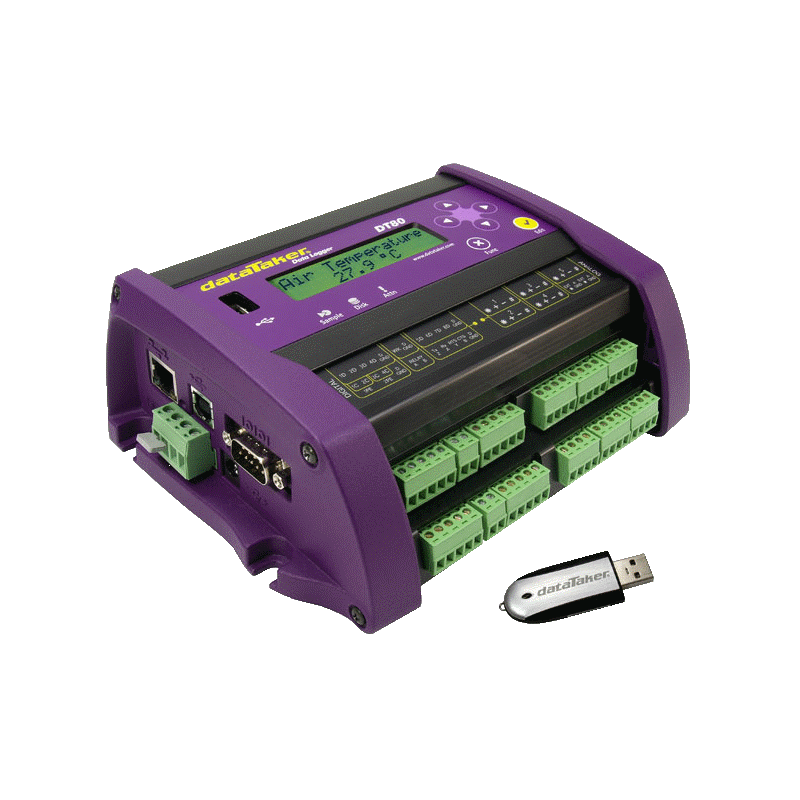
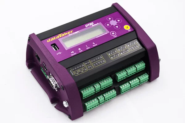
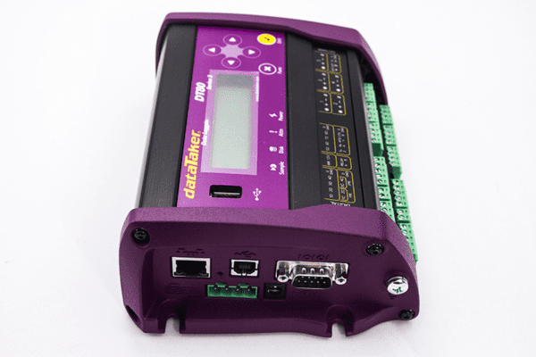
The DT80 Universal Input Data Logger

The new Series 4 version of the DT80 Universal Input Data Logger has increased sampling speed, measurement range, and programmable analog output.

The dataTaker DT80 Universal Input Data Logger provides an extensive array of features that allow it to be used across a wide variety of applications. The DT80 is a robust, stand-alone, low-power data logger featuring USB memory stick support, 18-bit resolution, extensive communications capabilities, and a built-in display.

The dataTaker DT80’s Dual Channel concept allows up to 10 isolated or 15 commonly referenced analog inputs to be used in many combinations. With support for multiple SDI-12 sensor networks, Modbus for SCADA systems, FTP and Web interface, and 12V regulated output to power sensors, the DT80 is a totally self-contained solution.

Versatile Measurement

Connect an array of sensors through versatile analog and digital channels, high-speed counter inputs, phase encoder inputs, and programmable serial sensor channels.

Temperature, voltage, current, 4-20mA loops, resistance, bridges, strain gauges, frequency, digital, serial, and calculated measurements can all be scaled, logged, and returned in engineering units or within statistical reporting.

Set up sampling, logging, alarm, and control tasks to suit your own requirements while interfaces for smart sensors, GPS, and other intelligent devices expand the DT80 flexibility.

Superior Data Storage and Communications

With the standard unit able to store up to 10 million data points (expandable) you can log as much or as little as you need. Overwrite or stop logging once allocated memory is full, archive data on alarm event, copy to USB memory, or transfer via FTP/ Email, the choice is yours.

Communications features include RS232, USB, and Ethernet, and connect to the DT80 locally, remotely through a modem, or over the Internet. The web interface allows users to configure the DT80, access logged data, and see current measurements as mimics or in a list using a web browser.

FTP/ Email provides data to your office over the internet or wireless network, without the need for polling or specific host software.

Read how the DT80 universal input data logger was used for Nitriding Process Temperature Trending in Industrial Heating Magazine.

Read More About the DT80 Intelligent Universal Input Data Logger:

Connecting a dataTaker DT80-Range Data Logger to a LAN

Power Metering with a DT80 Using WattNode Transducers

The World’s Fastest DT80

Specifications

Analog Channels
Analog Channels 5 analog input channels (expandable to 100*)
Each channel is independent and supports: one isolated 3-wire or 4-wire input, or two isolated 2-wire inputs, or three common referenced 2-wire inputs
2 Wire w/ Com. Ref. Terminal: 15 Channels (expandable to 300*)2 Wire Isolated: 10 Channels (expandable to 200*)3 or 4 Wire Isolated: 5 Channels (expandable to 100*)* Expansion requires optional CEM20
Fundamental Input Ranges The fundamental inputs that the DT80 can measure are voltage, current, resistance and frequency. All other measurements are derived from these.
Sampling Integrates over 50/60 Hz Line Period for Accuracy and Noise Rejection
Maximum Sample Speed: 40 Hz
Effective Resolution: 18 Bits
Linearity: 0.01%
Common Mode Rejection: >90dB
Line Series Mode Rejection: > 35dB
Sensor Excitation (Supply) Analog Channels:
Selectable 250µA, 213µA or 2.5mA Precision Current Source
4.5V Voltage Source
or Switched External Supply
General Purpose: Switchable 12V/5V Regulated Supply for Powering Sensors & Accessories (Max. 150mA)
Analog Output Isolated programmable 16-bit DAC: voltage 0-10V or current 0-14mA
Analog Sensors
Thermocouples Type: B, C, D, E, G, J, K, N, R S, T
Calibration Standard: ITS-90
RTDs Materials Supported: Pt, Ni, Cu
Resistance Range: 10Ω to 1MΩ
Thermistors Type: YSI 400xx Series, other Types*
Resistance Range: Up to 1MΩ
* Other Thermistor Types are Supported by Thermistor Scaling and Calculated Channels
Monolithic Temperature Sensors Type: LM34 – 60, AD590, AD592, TMPxx, LM135, LM235, LM335
Strain Gauge and Bridge Sensors Configurations: 1/4, 1/2 & Full Bridge
Excitation: Voltage or Current
4-20mA Current Loop Internal 100Ω Shunt or External Shunt Resistor
Digital Channels
Digital Input/Outputs 8 Bi-Directional Channels
Digital Input Type: 8 Logic Level (Max. 20/30 Volts)
Digital Output Type: 4 With Open Drain FET (Max. 30V, 100mA), 4 with Logic Output
Relay Output 1 Latching Relay, contacts (Max: 30Vdc, 1A)
Counter Channels
Low Speed Counters 8 Counters Shared with Digital Inputs
32 Bit Size, 10 Hz Max Count Rate
Low Speed Counters do not Function in Sleep Mode
Dedicated Counter Channels 4 High Speed Input or 2 phase encoder (quadrature inputs)
32 Bit Size, 100kHz Max Count Rate
2 Logic Level Inputs (Max ±30V)
2 Sensitive Inputs (10mV) for Magnetic Pick Ups (Max. ±10V)
Serial Channels
SDI-12 — 4 SDI-12 Inputs, Shared with Digital Channels
— Each input can support multiple SDI-12 Sensors
Generic Serial Sensor Flexible Option for Logging From Wide Range of Smart Sensors and Data Streams
Available ports: Serial Sensor Port (RS232, RS422, RS485) or Host RS232 Port*
Baud Rate: 300 to 115,200
* If used as a Serial Sensor channel then the Host Port is Not Available for Other Communications
Calculated Channels
General Combine values from analog, digital and serial sensors using expressions involving variables and functions.
Functions Arithmetic, Trigonometric, Relational, Logical and Statistical
Alarms
Condition High, Low or Within Range and Outside Range
Delay Optional Time Period for Alarm Response
Actions Set Digital Outputs, Transmit Message, Execute any DataTaker Command.
Scheduling of Data Acquisition
Condition High, Low or Within Range and Outside Range
Number of schedules 11
Schedule rates 10ms to days
Internal Data Storage Capacity: 128mb = approx 10,000,000 data points
Removable USB storage device Type:compatible with USb 1.1 or USB 2.0 drivers, e.g. Flash drive
Capacity: approx 90,000 data points per megabyte
Communication Interfaces
Ethernet Port Interface: 10BasteT (10Mbps)
Protocol: TCP/IP, Modbus (Master & Slave)
USB Port Interface: USB 1.1 (virtual COM port)
Protocol: ASCII command
Host RS232 Port Speed: 300 to 115,200 Baud (57,600 Default)
Flow Control: Hardware (RTS/CTS), Software (XON/XOFF), None
Handshake Lines: DCD, DSR, DTR, RTS, CTS
Modem Support: Auto-Answer and Dial Out
Protocols: ASCII Command, TCP/IP (PPP), Serial Sensor, Modbus
Serial Sensor Port Interface: RS232, RS422m, RS485
Speed: 300 to 57,600 baud
Flow Control: Hardware (RTS/CTS)
Software: (XON/XOFF), None
Protocols: Modbus (master & slave), Serial Sensor
Network TCP/IP Services
Network Ethernet and/or Host RS232 (PPP) Communication Ports
Command Interface Access the ASCII command interface via TCP/IP
Web Server Access Current Data and Status from any Web Browser
— Custom pages can be defined — Download Data in CSV Format
— Command Interface Window
— Define Mimic Displays
Modbus Server(slave) Access current data and status from any Modbus client (e.g. SCADA system)
Modbus Client (master) Read/write data from modbus sensors and devices including PLC’s, dataTaker loggers, modbus displays, etc.
FTP Server Access logged data from any FTP client or web browser
FTP Client Automatically upload logged data direct to an FTP server.
System
Display and Keypad Type: LCD, 2 Line by 16 Characters, Backlight
Functions: Channel Data, Alarms, System Status
Keypad: 6 Keys for Scrolling and Function Execution
Status LEDs: 4 (Sample, Disk, Attention, Power)
Firmware Upgrade Via: RS232, Ethernet, USB or USB disk.
Real Time Clock Normal resolution: 200µs
Accuracy: ±1 min/year (0°C to 40&degC), ±4 min/year (-40°C to 70°C)
Power Supply External Voltage Range: 10 to 30 Volts DC
Internal battery: 6Vdc 1.2Ahr lead acid
Peak Power: 12 W (12VDC 1A)
Average power Consumption Using 12Vdc external power source
1 Sec Sampling: 1350 mW
5 Sec Sampling: 500 mW
30 Sec Sampling: 135 mW
5 Min Sampling: 70 mW
1 Hr Sampling: 60 mW
Typical Operating Time from internal 6Vdc, 1.2Ahr battery
1 Sec Sampling: 6.5 hours
5 Sec Sampling: 1 day
1 Min Sampling: 10 days
1 Hr Sampling: 3.5 months
Physical Environment
Construction Powder Coated Steel & Anodized Aluminum
Dimensions 180 x 137 x 65mm
Weight 1.5kg (4kg shipping)
Operating Range Temperature: -45°C to 70°C (Reduced LCD Operation Outside Range: -15°C to 50°C)
Humidity: 85% RH, Non-condensing
Resources Included
Resource CD Includes software, video training and user manual
Comms cable USB cable
Line adapter 110/240Vac to 15 Vdc, 800mA

Software

dEX data logger software is an intuitive graphical interface that allows you to configure your data logger, view real-time data in mimics, trend charts or tables and retrieve your historical data for analysis.

Browser-based Solution

dEX comes pre-installed on every logger in the DT80 range. The software loads in your web browser so there is no need to install cumbersome applications on your computer. Being browser-based, dEX will work on all major operating systems including Windows, Mac and Linux.

Configuration Editor

The configuration editor allows you to view, edit and save logger configurations in an easy-to-use Windows Explorer style user interface. The configuration tree view allows definition of measurement schedules and measurements.

dataTaker dEX Software Configuration Editor

Wiring diagrams show available wiring configurations for each sensor type. Configuration can be stored and retrieved on either the logger or a local computer.

Mimics and Charts

Mimics are organized into panels which can be modified to highlight custom alarm conditions or data grouping. Mimics include dials, bar graphs, thermometers, etc. Real-time chart recorder mimic allows you to view trends and historical data over a custom time/date range. Up to 16 mimics can be displayed on up to 5 mimic pages.

dataTaker dEX Software Mimics and Charts

Minimum System Requirements

• Web Browser – Internet Explorer (IE7 or later), Safari, Google Chrome, Firefox
• Adobe Flash Player (10 or higher)
• Screen resolution of 1024 x 768

dEX is available as an Android App in the Google play store or and Apple app store.

Accessories