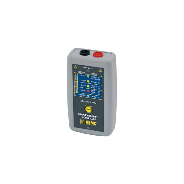
AEMC L261 TRMS AC Voltage Data Logger

  • 1 Input channel with banana connectors
  • Voltage input range of 0-600 VAC/VDC
  • 64 Samples/cycle
  • Storage rate of 8x per second to 1/day
  • Store up to 240,000 measurements
  • USB communication interface
  • Simple LED status display
  • Battery powered

Call for configuration and price. 1-800-956-4437

Description

The AEMC L261 TRMS AC Voltage Data Logger is a one channel, battery-powered recording device for voltage measuring, monitoring, and troubleshooting. Line tracking is performed such that 64 samples over one line cycle are taken. Frequency tracking is performed over the range of ±2Hz around the nominal line frequency (50 or 60Hz). Harmonic measurements are calculated from these 64 samples (Harmonics are only available from the Simple Logger® II Control Panel within the DataView® software).

The AEMC L261 TRMS AC Voltage Data Logger records True RMS at a rate of up to eight times per second. The measurement process is performed no more than eight times per second. TRMS calculations are performed on a single line cycle. This means that the input(s) are ignored between measurement intervals. The main advantage of the logger is its ability to perform a variety of recording tasks with easy and intuitive setup from a computer using DataView® software.

Analog information on the input is sampled and converted to a digital signal. This digital signal is processed and stored along with scale and time information. An optically isolated Universal Serial Bus (USB) port provides for the transfer of data from the instrument’s internal memory to the computer for analysis.

Common applications are surge and sag recording, long-term supply monitoring, industrial and commercial monitoring, voltage harmonics, machine monitoring and finding intermittent voltage problems.

Applications
  • Surge and Sag recording
  • Long-term supply monitoring
  • Industrial, commercial, residential monitoring
  • Monitor voltage harmonics
  • Find intermittent voltage problems
  • Machine monitoring

Specifications

Electrical
Channels One
Input Connection Two recessed banana jacks
Voltage Range 0 to 600V AC/DC
Resolution 0.1 V
Accuracy (50/60Hz) 0 to 5V: unspecified
5 to 50V: ±(0.5% of Reading + 1V)
50 to 600V: ±(0.5% of Reading + 0.5V)
Sample Rate 64 samples/cycle
Storage Rate Programmable from 125mS to 1 day
Storage Modes Start/Stop Mode
First In First Out Mode (FIFO)
Extended Time Recording Mode (XRM)
Recording Length 15 minutes to 8 weeks, programmable using DataView
Memory 240,000 measurements (512KB) The recorded data is stored in non-volatile memory & retained even if the battery is low or removed.
Communication USB 2.0 optically isolated
Power Source 2 x 1.5V AA-cell Alkaline batteries
Battery Life 100 hours to >45 days (dependent on storage rate/recording length)
Mechanical
Dimensions 4.94 x 2.75 x 1.28″ (125 x 70 x 32mm)
Weight (with battery) 6.4 oz (180 grams)
Case UL94-V0
Vibration IEC 68-2-6 (1.5mm, 10 to 55Hz)
Shock IEC 68-2-27 (30G)
Drop IEC 68-2-32 (1m)
Environmental
Operating Temperature 14° to 122°F (-10° to 50°C)
Storage Temperature -4° to 140°F (-20° to 60°C)

Recording Modes

Start/Stop Mode

In this mode the operator selects a storage rate from predefined values from 8 per second to 1 every day, then selects a start and stop time. Data is recorded at this rate until the memory is filled or the end recording time and date is reached. The logger then stops recording and goes into standby mode retaining the recorded date.

First In First Out Mode (FIFO)

The operator makes the data storage and recording length selections as described above. If the memory fills before the end date and time occurs, the logger will discard the oldest stored data point and add a new one. This process will continue until the end recording date and time is reached.

Extended Time Recording Mode (XRM)

This unique recording mechanism provides for continuous recording over a longer period of time without the need for the operator’s selection or adjustments. The operator selects a starting storage range from predefined values from 8 per second to 1 every day and a recording length. The logger will store data at the rate selected until the memory is filled. The logger will then discard every other stored sample beyond the first one, freeing up half the memory for continuous recording. New samples will be stored at half the previous storage rate, matching the interval with the remaining stored data. This process will repeat each time the memory fills until the operator stops the recording manually, the end recording date and time is reached or the battery runs down.