
For Series 3 dataTaker devices
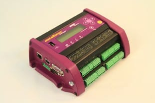 The new Series 3 DT80 range data loggers from dataTaker are intelligent monitoring solutions used the world over in almost every imaginable field and application. CAS DataLoggers Application Specialists have put together this how-to guide so users can check the calibration of their DT80 range data loggers. Just complete the 5-step procedure described below–if the logger fails any of these tests, then it should be returned to dataTaker or your local distributor for calibration.
All measurements should be conducted in a constant temperature-controlled environment (i.e. ±2°C) during the course of testing. This prevents temperature drift effects of the reference voltage and reference resistances. The limits shown in the sample report assume that the test environment is between 5°C and 40°C. For the same reason, the datalogger needs time to “soak” in a temperature-controlled environment before calibration can be performed. The unit must be powered up and left to sit at the test temperature for a minimum of 4 hours before calibration.
Also note that before conducting any test, the logger must first be earthed. Do this by connecting an earth wire to the earth point on either side of the data logger, or for older models without the earth points, use the negative (‘–‘) input of the power terminal block immediately below the Ethernet port on the left side of the datalogger.
All tests assume that the operator is familiar with using the dataTaker command language and a suitable terminal application such as DeTransfer.
Equipment required:
1x Programmable Precision voltage source*
1x 100Ω 0.05% 5ppm or better
1x 1000Ω 0.05% 5ppm or better
*The high-voltage range of the logger has an input impedance of approximately 110kOhm. Ensure that the voltage source has low output impedance or the test results will be invalid.
- Perform a self-test of the datalogger by issuing the TEST command and observing the result. The logger will return various test results and an overall Pass/Fail result.
- Now perform a low-voltage range test. Using a precision voltage source, apply these known voltages to the datalogger:
- +25mV, +250mV and +2500mV
- -25mV, -250mV
Measure these voltages using the following wiring configuration and dataTaker commands:
Wiring Configuration
Connect the applied voltage between the positive (‘+’) and negative (‘–‘) terminals of analog channel 1.dataTaker Commands
RA1S 1V(FF6)Record and check results against the limits shown in the sample report.
- Now perform a high-voltage range test: Using a precision voltage source, apply these known voltages to the logger:
- +0.25V, +2.5V and +25V
- -0.25V, -2.5V and -25V
Measure these voltages using the following wiring configuration and dataTaker commands.
Wiring Configuration
Connect the applied voltage between the ‘+’ and ‘–‘ terminals of analog channel 1.dataTaker Commands
RA1S 1HV(FF6)Record and check results against the limits shown in the sample report.
- Perform a low-resistance range test. Apply the following known resistance to the logger:
- 100Ω (0.05% 5ppm or better)
This test will use the “II” current excitation (2.5mA).
Measure the resistance using the following wiring configuration and dataTaker commands:
Wiring Configuration
Connect the known resistance using a 4-wire configuration to analog channel1.dataTaker Commands
RA1S 1R(4W,II,FF3)
Record and check results against the limits shown in the sample report. Move the connector to Channel 2 and repeat. Modify the command to reflect the new channel under test.RA1S 2R(4W, ll,FF3)
Continue the above process, moving the connector to each successive channel of the dataTaker until all channels have been validated. - Finally, perform a high-resistance range test. Apply the following known resistances to the logger:
- 100Ω (0.05% 5ppm or better)
- 1000Ω (0.05% 5ppm or better)
This test will use the “I” current excitation (213uA).
Measure the resistances using the following wiring configuration and dataTaker commands:
Wiring Configuration
Connect the known resistances using a 4-wire configuration to analog channel 1.dataTaker Commands
RA1S 1R(4W,I,FF3)
Record and check results against the limits shown in the sample report. Move the connector to Channel 2 and repeat. Modify the command to reflect the new channel under test.RA1S 2R(4W, l,FF3)
Continue the above process, moving the connector to each successive channel of the dataTaker until all channels have been validated.