Using Grant Dataloggers to Connect Strain Gauges, Load Cells and More
Bridge sensors are commonly used in many data logging applications including construction, building conservation and the manufacture of pressure sensors. Bridge sensors include strain gauges, pressure sensors and load cells. A bridge sensor consists of four resistive elements of which one or more change their resistance with a change in the input parameter being measured. In this technical article CAS DataLoggers outlines how connection is performed when logging with a Grant Squirrel 2020/2040 Data Logger.
Bridge Sensors: Overview
- In a full bridge, all four elements change their resistance
- In a half bridge, two elements change their resistance and two are fixed
- In a quarter bridge, only one element changes its resistance and the other three are fixed.
Note that for the greatest accuracy, the fixed resistors must be precision, low-temperature coefficient types. The three types of bridge are shown in Figure 1 below.
Figure 1: Bridge Sensor Types

All of the above have four wires connected to the bridge, and so they are known as 4-wire bridges. In a 4-wire system, the voltage drop in the power supply leads is assumed to be small so the bridge input voltage is measured at the power supply. However, if there is a significant resistance in the supply wires, then the voltage measured at the supply and bridge ends of the supply wires will be different, which could lead to measurement errors.
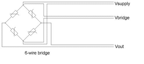
In this case it is necessary to use a 6-wire bridge system where two wires supply power to the bridge, two wires measure the voltage actually present at the bridge (thus removing any voltage drops in the power supply leads) and two wires measure the bridge output as shown in Figure 2 below.
Figure 2: 6-Wire Bridge System
Grant Squirrel Data Loggers
The SQ20xx range of dataloggers can be used to measure all of the above types of bridge sensor with the total number of inputs being dependent on the logger type AND the type of connection made. For example, a 6-wire bridge requires two differential voltage inputs for each measurement but using a half or quarter bridge in 4-wire connection could be done with one single-ended voltage input to measure the bridge supply voltage, one single-ended voltage input to measure the fixed half bridge output voltage, and then one single-ended voltage input to measure for each sensor (although this would give the worst accuracy). Thus a SQ2020 2F8 datalogger could measure four 6-wire bridges fully differentially, or sixteen half or quarter bridges using single-ended inputs including the two high voltage inputs. The best compromise would be to use one differential voltage input to measure the common bridge supply voltage at the logger and then use a differential voltage input for each bridge.
The logger’s sensor power output can be used to power the bridge sensor so long as you take care to ensure it’s not overloaded, since bridge sensors are often low-impedance. For example, a 330-Ohm bridge running from the 5V sensor supply draws about 15mA. However, the 5V supply can only give 50mA maximum and so it could only have three full bridges connected to it, although this can easily be increased by using an external power supply.
Making the Measurement:
Strain gauges change resistance when stretched or compressed. The strain-resistance relationship is given by:
Strain = ∆L = 1 * ∆R
L G R
Where:
L is the initial length;
∆L is the change in length;
G is the gauge coefficient (given by the gauge manufacturer);
R is the initial resistance;
∆R is the change in resistance.
However, it is difficult for the datalogger to actually measure the small resistance changes, so it’s much better to use the formula rearranged in terms of voltage which is:
Strain = 4 * _Vout_
G * N Vbridge
Where:
G is the gauge coefficient as before;
N is the number of active bridge elements (1 for quarter, 2 for half and 4 for full);
Vout is the bridge output voltage;
Vbridge is the bridge supply voltage.
The following example shows how to set up a SQ2020 2F8 to measure two 4-wire full bridge strain gauges for gauges with a gauge coefficient of 2.0. The equation you need to calculate the strain is:
Strain = 4 * _Vout_ = 4 * _Vout_ = 0.5 * _Vout_
G * N Vbridge 2.0 * 4 Vbridge Vbridge
While it is possible to get the logger to recalculate the constant part of the expression (4/G*N), it uses up more equation space in the logger, so it’s better to calculate it beforehand as shown above.
Before entering the equations in the calculated channels, the differential input voltage need to be selected and named in the Logger Setup window in SquirrelView software, with the 5V sensor power turned on as shown below. Only one Vbridge measurement is required since the bridges are 4-wire, so the bridge supply voltage is measured at the logger. The voltage drop along the wires is assumed to be negligible.
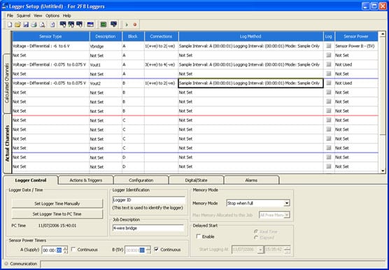
The channels are set to Sample Only since only the resultant strain output is of interest. The strain is obtained by using calculated channels as shown below. First enter the equation as described above.
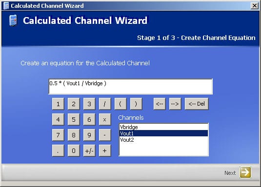
Then set the units and the correct number of decimal places. Ensure that the ‘Log’ box is checked.
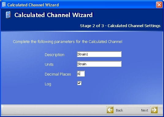
Finally, check that everything has been entered correctly.
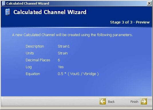
Repeat the above procedure for the second channel. After sending the setup to the logger it will now be able to log and display the strain imposed on the strain gauge bridge.

