
Infinite BSC-50 With Remote Alarming System
 CAS DataLoggers provided the data logging solution for an electric utility company that needed to send alarms from remote stations in the event that the local power grid went down, and in other special cases including operational faults and security breaches. The entire time a substation was off the grid, an area was without power, so an advanced warning system for ground fault events was critical as well as fault detection and diagnosis. Management saw the need for a remote alarming system with SMS alarm messaging to warn personnel in case of a fault event and which would also send data to activate LEDs on a status screen to pinpoint the exact spot at which the power failure occurred. This system also needed to be cost-effective and have long battery life for years of worry-free operation.
Installation
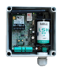
The utility company installed 200 Infinite BSC-50 Remote Alarming Systems in the immediate vicinity of its power substations, connecting these dataloggers with an Infinite SCOM-100 GSM/GPRS controller to receive their data and alarm messages. The BSC-50 devices were ideal for supervising substation operational status, featuring 4 user-configurable digital inputs to identify the binary status of operations/faults in the form of Push/Pull or 0-1 and 1-0 transition. An optional version was available featuring 2 digital inputs along with 2 analog inputs to measure and alarm on threshold and limit breach and an excitation output for powering external transducers.
An ultra-low-power microcontroller enabled alarm condition detection, subsystem power switching, and overall system control. Both versions featured quad-band GSM network compatibility and a serial port for PC connection. Each logger had an uninterruptible power supply from one or more built-in lithium-ion power cells providing more than 10 years of operation. The devices could operate on normal power and in the event of a power loss, they could be powered from the battery completely.
Usage
 The user-friendly SCOM-100 DIN rail-mounted controller provided the power station with alarming and remote control using SMS. The main unit incorporated a quad-band (850/900/1800/1900MHz) GSM/GPRS modem, 2 analog inputs, 4 digital inputs, 4 power relay outputs, and a serial RS-232 port. Front panel LED indicators displayed control and digital I/O states, and a variety of I/O expansion units (digital and analog I/O) could be cascaded on the serial I/O expansion bus if needed. The device featured several operation modes, including emergency stop, low power operation and more. All setup and control were simplified using a mobile phone; personnel simply inserted a SIM card with a name and phone number in the phone list and pressed the startup button as the controller powered on. Simple ASCII configuration commands handled unit setup and control, and several commands could be packed in one SMS. Additionally, the controller’s RS-232 interface could be used to both set up and test the unit using a PC or an ASCII terminal. The rich command set featured commands for configuring input alarm parameters, setup of time scheduled programs, control functions like on/off and PID control, defining user groups, and controlling system output with time-related parameters. The unit included free bundled SCOM Configurator PC software for convenient setup and commissioning complete with easily upgradeable firmware.
An OPC driver was also available for connecting the SCOM-100 controller to common SCADA systems in a wide variety of industries and applications. Again, a few SMS ASCII commands were all that was needed for quick, convenient setup and control of the GPRS functionality–static IP or VPN network addresses for the SCOM-100 units were not required. The OPC server could support several distributed SCOM-100 units, limited only by the total I/O number.
At each substation, special fault detection and diagnosis relay was installed that detected earth ground faults and provided a plain contact as an alarm in the case of a fault. The BSC-50 GSM/GPRS dataloggers monitored these faults and limit breaches and then transmitted respective coded messages via SMS to a control center. The BSC-50s were also programmed to transmit “I am alive” messages at regular schedules to the control center to relay their operational status, with a maximum of 20 users/recipients. When an earth ground fault was detected in a substation, that substation was then automatically taken offline, and manual or remote operations were then needed to place the substation back on the grid. If the fault persisted, then the substation’s local automation ensured that the station was not placed back on the grid.
At the control center, a PC was installed running the monitoring software that logged, monitored and reported the operational status of the remote alarming dataloggers. The PC ran Windows XP Pro executing WA Manager software and was also connected to a GSM modem. Also in the control center, a mimic diagram showing the geographic location of the substations and their BSC-50 devices was installed, with built-in red-colored LEDs at each substation. These LEDs were cabled to the M2M (machine to machine) SCOM100 alarm receiver device, connecting to the controller’s digital outputs. When an alarm occurred at a BSC-50, two messages were immediately sent: one to the control center monitoring station running WA Manager, and one to the receiver device to switch on an LED at the mimic diagram. As soon as the fault was rectified, the LED could be manually switched off using a switch on the main mimic diagram.
Benefits
The utility company benefitted immediately from installing the fault detection and diagnosis remote alarming system to monitor ground current at its power substations. The SCOM controller received SMS messages from the remote dataloggers and lit the LED lamps on a mimic diagram so that users at the control center could now both visualize the location of the faults and see the sequence of failing substations in order to perform remote operations if possible or to order a maintenance crew to visit a specific point on the grid to reroute power and maintain power in the areas which had been taken off the grid. The system was very cost-effective, with one product handling all the remote monitoring and sending the data back to the SCOM receiver and the control room mimic.
The estimated time reduction in identifying and rectifying problems on the grid was very high. The only procedure used previously was to send a maintenance crew to visit the substations and see which station’s outdoor lamp was off and report back to the control center. Then operations to reroute power had to be made on a time-intensive trial and error basis. Using the new remote alarming system, management could instantly see the LEDs on the mimic and know just where to send the crew, which kept the time substations were off the grid to a minimum by improving problem detection and response times.
For further information on the Infinite BSC-50 Remote Alarming System, other remote monitoring data loggers, fault detection and diagnosis or to find the ideal solution for your application-specific needs, contact a CAS Data Logger Application Specialist at (800) 956-4437 or request more information.