
Introduction
The Peripheral Sensor Interface (PSI5) communications interface is a 2-wire serial interface found in the automotive industry. It is used in millions of vehicles to interface sensors like accelerometers to Electronic Control Units (ECU) in applications for airbag systems. Promoted by major auto suppliers such as Bosch and Continental, the PSI5 interface has been in use for more than 10 years and has shown itself to be both robust and reliable. Figure 1 below shows the PSI5 telegram definition.
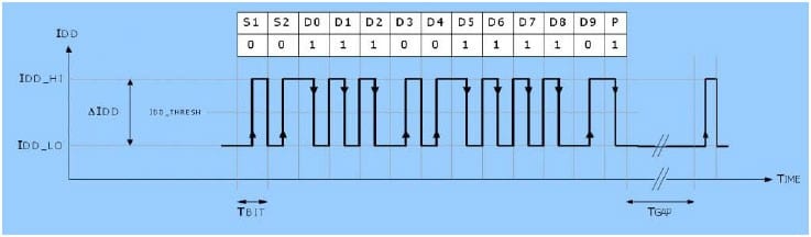
Figure 1: PSI5 Telegram Definition
To minimize the number of wires going to the sensor, the physical layer of PSI5 is implemented as a 2-wire interface that carries both the signal and power. The sensor data is sent as a series of current pulses which ride on top of the normal sensor supply current. This allows the interface to communicate at up to 250K bits/second and provides EMC compatibility for conducted and radiated emissions. The standard data packet consists of 13 bits: 10 bits of data, 2 start bits, and a parity bit (see Figure 1 above). The data is encoded using a Manchester coding scheme where a 0 corresponds to a rising edge in the middle of the bit transition time and a 1 by a falling edge in the middle of the bit. Typically, a dedicated receiver IC is used to read the current signal and extract the data.
Implementation
A sensor manufacturer was looking for a system to simultaneously test multiple PSI5 sensors using this interface. Rather than try to build a custom solution around the dedicated interface chips, they were looking for an off-the-shelf data acquisition solution that could be programmed to read the raw signal and extract the data. For this project, an ADwin-X-A20 Real-Time Data Acquisition System was selected. A simple comparator circuit was used to convert the current signal to a digital waveform that could be read with standard TTL logic.
The ADwin system features 8 high-speed digital I/O channels allowing up to 8 sensors to be read at the same time. For each digital input, a simple state machine was implemented in software to monitor the incoming data, look for the start bits, and read and then decode the data.
Figure 2 shows the state machine to read one input. The minimum bit time corresponding to a 0 was 40 microseconds; therefore, to allow for small variations in the timing, the state machine was set up to read the inputs at 8 times the expected clock rate, or 5 microseconds. A watchdog timer was also provided to allow the state machine to reset in the case of a partial or corrupted transmission. Figure 3 lists the ADBasic code for the state machine to reading one sensor. For testing, a second ADwin system was configured to generate various data packets to verify that they could be read correctly.
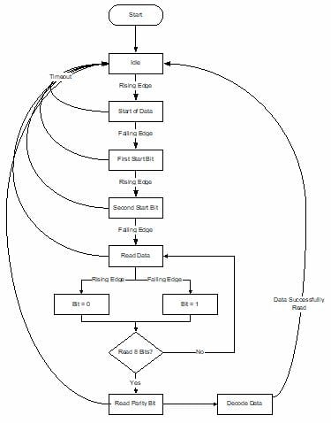
Figure 2: State Machine to Read PSI5 Data
For this project, it was quite straightforward to create a simple state machine using the CASE structure available in the ADBasic programming environment. Figure 3 shows a portion of the program to look for the start of a word, and read and decode the datagram. The ADwin system was programmed to execute this EVENT: loop every 5 microseconds to match the standard timing of the PSI5 signal.
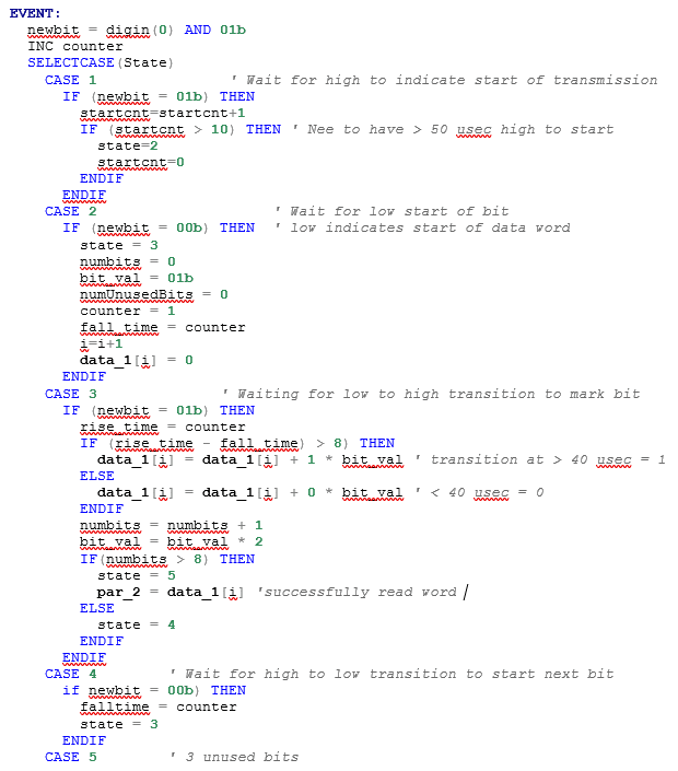
Figure 3: Sample ADBasic Code For The State Machine to Read One Sensor
Benefits
The deterministic, real-time capability of the ADwin system allowed the data to be read reliably without the need for specialized receiver ICs. The flexibility of the software enabled the different scenarios and failure mechanisms to be tested quickly and easily. By using the ADwin-X-A20, the customer was able to test 8 devices in parallel, dramatically reducing the hardware required.
For more information on ADwin Real-Time Systems or to find the ideal solution for your application-specific needs, contact a CAS Data Logger Applications Specialist at (800) 956-4437 or request more information.