
Winlog Lite SCADA Software
Winlog Lite SCADA Software enabling a wide range of application development and online browser-based access. Factory and plant managers can benefit from using a dataTaker DT8X Series Data Logger to create and configure their Winlog Lite projects.
Winlog Walkthrough:
- Prerequisites:
- Requirements:
- dataTaker DT8x datalogger running firmware V 7.12 or above
- PC with Winlog Lite installed (available from sielcosistemi.com)
- dataTaker DeTransfer software
- Network connection between the PC and the dataTaker
- Method
-
3.1 Check dataTaker settings
-
Write down the dataTaker MODBUS_SERVER and ETHERNET profile settings. These contain the information that you’ll need to communicate via Modbus RTU TCP. If you are using an automatic IP address, then you should consider changing this to a static IP address—consult your network administrator about this.
When using Modbus, the values are transmitted in integer (whole number) form. This means that the values are all rounded to the nearest whole number. To maintain decimal precision, you can specify a scale factor for the numbers transmitted over the Modbus connection, then divide the value on the receiving end. This is done via the SETMODBUS command.
To scale the dataTaker’s channel variables 1-30 by 100 (which would give you 2 decimal places), you would enter the following dataTaker command: SETMODBUS 1..30CV MBI 100.
Note that when using the MBI format, the valid range is -32768 + 32767, hence if you use a divider of 100, then you must have values between -327.68 + 327.67.
3.2 Create and set up a Winlog Lite project
| Open up the Winlog Lite ‘Project Manager’ by clicking [Start] Programs Winlog Lite Project Manager |
|
| Click the ‘Create new project’ button | 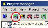 |
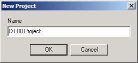
| Give the project a name and Click ‘OK’ The project shall now appear in the project tree. |
 |
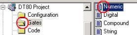
| In the project tree, expand the project that you just created and click Configuration, then double-click Channels |
 |
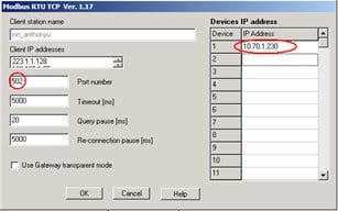
| In the Channels configuration window, select Modbus RTU TCP from the drop-down. The Options window should now appear. |
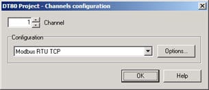 |
| In the options window, change the Port number to the value of the TCPIP_PORT parameter in your dataTaker and add the IP Address of your dataTaker to the IP address list. Click OK to close the options window, then OK again to close the channels configuration window. |
 |
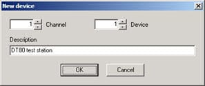
| Double-click Devices. |  |
| Click Add, the New device dialog will appear. Use the default Channel and Device settings (1,1) and enter a description for your device.
Click OK to close the dialog, then OK again to close the devices window |
 |
3.3 Adding Measurements (Gates) to the Project:
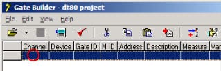
| In the project tree, click Gates then double-click Numeric. The Gate Builder window will appear. |
|
| To add or modify a gate, double-click on a blank or gate line. This opens the Gate Properties window. |
 |
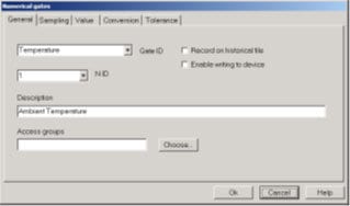
| On the General tab, the essential properties which must be defined include: Gate ID – name your gate N ID – a number for your gate Description |
 |
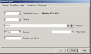
| On the Sampling tab, choose the Channel and Device to be 1. The Address is mapped to the channel variable you wish to view, but is 30,000 minus one (40,000 if you need to read/write). i.e. if you wish to view 23CV then you enter address 30022Change Sample to ‘Always’ and define your sample frequency |
 |
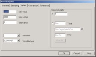
| On the Value tab, enter the Maximum and Minimum values for your variable Change the Variable Type to S_WORDEnter the number of Decimal Digits you will use (this is to counter the scaling performed when setting up the dataTaker) |
 |
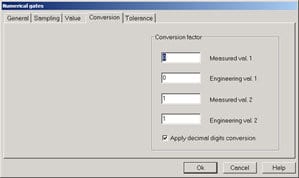
| On the Conversion tab, select ‘Apply decimal digits conversion’. You may leave the rest of the fields as default Click OK to finish and add your gate Save the changes on the Gate builder window and close |
 |
3.4 Creating a Template/Dashboard
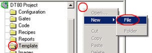
| In the project tree, click Template Right-click in the blank space and select New File A file with the name ‘No Name’ will appear Double-click the No Name file to open it. The Template Builder will appear. |
 |
| In the template window, you can choose a range of different controls and images to place on your dashboard. | 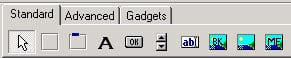 |
| Place the controls on the template, insert buttons, gauges, pictures, charts etc.
Remember to save the template as you build it up. |
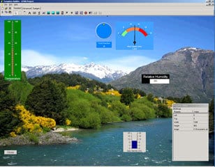 |
| To assign variables to your controls, click on the Gates option in the property editor, on the left of the screen. Follow the prompts to add your gates to the list. | 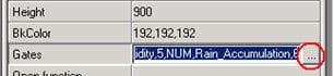 |
Once you have completed adding components to your dashboard, save your template and choose the template window.
3.4 Executing Your Template/Dashboard
To run your dashboard, open the Project Manager and right-click on the project name and select Execute.
Once the project opens, click Supervision, Template, Template name. If you would like a template to automatically open whenever you execute the project, you can follow this procedure.
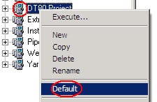
| First, let us make the current project the default.
To do this, right-click on the project name and then click Default. Now, the project can be executed from the start menu under: |
 |
| In the project tree, click
Configuration Template |
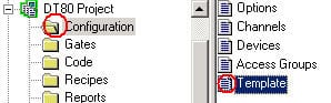 |
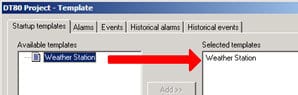
| The Available Templates list can be seen on the left. From this list, double-click the template you wish to open at startup. This will transfer it to the Selected Templates list.
Click OK |
 |
For further information on the Winlog Lite SCADA Package with DT80-Range Data Loggers or for additional technical support, contact a CAS Data Logger Technical Specialist at (800) 956-4437 or request more information.