Working With the Bestselling DT8X Series of Flexible Data Logger
The popular dataTaker line of data loggers are commonly employed for monitoring environmental conditions including wind speed and wind direction. Given the flexibility of the DT8X series dataloggers, there are several options in how these measurements are configured. Described here is a set-up that was used successfully with a weatherstation.
Wind speed measurements with DT8x data loggers are very straightforward. Most common types of anemometers provide a frequency output in the form of a simple switch closure output that can be used with the counter input of the data logger. All of the loggers in the DT80 series offer at least 4 high speed counter inputs that are suitable for these types of measurements. Programming the data logger is a simple matter of setting a schedule to periodically read the counter input and set up a scaling equation to convert counts to wind speed. While it may seem that using the frequency measurement function might also work, this approach suffers problems during the measurement of very low frequencies that are present at low wind speeds.
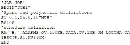
For example, if the wind sensor is connected to high speed counter input 1 and it provides an output with a frequency of 1Hz = 1.25MPH, the program using the logger command language in deTransfer would look like this:

In this example, since we are reading the counter every 10 seconds, the scaling has been adjusted to take into account the sample interval. Note also that the R option has been used when reading the counter to reset the count to 0 after each reading.
Often, what is desired is not the instantaneous wind speed as measured above (actually it is the average over a 10-second window) but rather the average over a longer period of time, for example a 3-minute window along with the peak speed during this time. The statistical capabilities of dataTaker dataloggers provide a simple way to obtain this data:
in DeTransfer:

In this example the statistical schedule is set to sample every 10 seconds to collect the intermediate data and the main schedule is set to return the average and the maximum value from this data every 3 minutes. In Delogger or dEX it is simply a matter of configuring the appropriate statistical sample rate and checking the appropriate boxes on the channel configuration screen.
Most wind direction sensors provide a variable resistor (potentiometer) that provides a resistance proportional to wind direction, so it is a matter of configuring the data logger to measure this resistance and then to set a scaling equation to convert the resistance to a direction (0-360 degrees). For example, assume that the wind direction sensor provides an output of 0 – 20,000 ohms for 0 – 360 degrees and that it is aligned so that 0 ohms corresponds to 0 degrees(North).
This example highlights 2 typical measurement issues that commonly arise. First, because the wind direction sensor is typically mounted a fair distance from the data logger (50-100 feet away), measurement of small resistances that occur when the direction is just slightly east of north suffer from error due to the parasitic resistance of the cabling. To overcome this, it is recommended that a 4 wire resistance measurement be used. A 4 conductor will be run from the analog input of the data logger to the wind direction sensor with one pair of wires connected to the – and # terminals and the low side of the potentiometer, one wire from the * terminal to the high side of the potentiometer and one wire from the + terminal to the center or wiper terminal. The second issue is that the logger can only measure a maximum of 10,000 ohms. The solution, as described in the article “Making High Resistance Measurements with DT8x Data Loggers” is to add a 10k resistor in parallel with the resistance of the wind direction to reduce the range or resistance that the data logger sees to 0-10,000 ohms.
In deTransfer, if the direction sensor is connected to input 2, the sample for the wind direction measurement is:

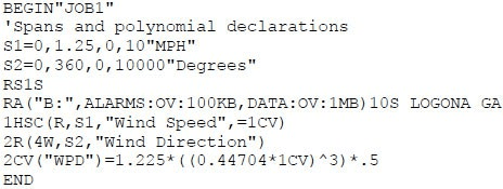
One commonly used parameter in site evaluation for wind turbines is wind power density, which is a measure of the energy in a standard volume of air moving past the turbine express in units of watts/m2. The wind power density (WPD) is: WPD= ½*p*V3
Where p = density of air, nominally 1.225 kg/m3
V = air velocity in m/sec2
This calculation can be easily implemented using the calculation capabilities of the datalogger along with internal variables. Putting it all together:
In deTransfer:

In Delogger and dEX, simply store the result of the wind speed into 1CV using the assign to channel variable option and the calculation would be entered in the calculation box.

